for Nuclear Power Plants (NPPs)
or any other high-rise structures
by Jose Antonio Abell Mena and Boris Jeremic (May 2015)
All example developed using the Real-ESSI Simulator.
A full 3 dimensional seismic wave field was created using a simple finite element model, as shown below
This wave field is rather simple, created with a point source at shallow depth in a 3 layer elastic media. Waves propagate, refract at layer boundaries (turn more "vertical") and, upon hitting the surface, create surface waves (in this case, Rayleigh waves).
Focusing our attention to a location of interest (where an NPP or any other structure will be located, vertical blue line), as shown below, we observe significant surface waves, in addition to refracted body waves (from layers).
Developed is a six component (6C) wave field, which in general has 3 translations and 3 rotations. In our case (as shown), out of plane translations and out of plane rotations are not developed, however this simplification will not affect conclusions that will be drawn. A seismic wave field with full 3 translations and 3 rotations (6C) will only emphasize differences that will be shown later.
Developed 6C wave field is shown below when it is input into a local free field model (only one half is shown, although a full 3D model was simulated):
Please note that seismic motions are input in an exact way, using the Domain Reduction Method (by Bielak et al.) and how there are no waves leaving the model out of DRM element layer (4th layer from side and lower boundaries).
If we now place an NPP model (containment and auxiliary building) on top of the free field model, and input the same free field motions, results, shown below, present a realistic Earthquake Soil Structure Interaction (ESSI) behavior. Please note that apparent penetration of auxiliary and containment building is not real, we have just amplified displacements (post-processing) so that they are easier to observe.
Note also that only one half of the model is shown in this post-processing for easier visualization of displacements, although a full model was simulated.
It is worth noting that outgoing wave field is now present, representing only the radiation damping of the NPP structure itself. It is also important to note that very little if any of that additional wave field is returning into the model, that is, the additional wave field is damped out in the outer layer.
If we now use developed 6C wave field, and ONLY use the HORIZONTAL component at the future location of an NPP, we can develop a one component (1C) wave field that represents a 1C vertical shear wave propagation.
Figure below shows the original 6C seismic field (blue), location of a point of interest (black point at the surface) and the 3 components of displacements and rotations that are present from 6C motions.
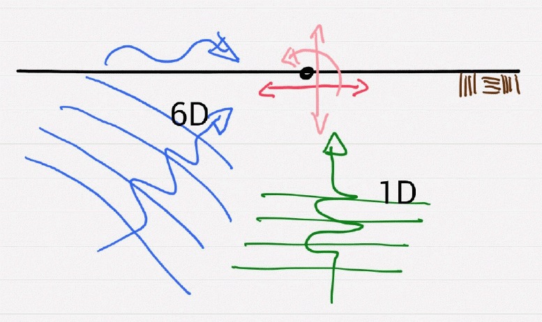
By picking only horizontal component of 6C motions (in our case really only 3C) at the surface, we can develop 1C motions (by doing a deconvolution) shown in green.
This is usually done in practice and research, from a full 3C recording (only translations are recorded, rotations very rarely) one horizontal direction is chosen, and used to developed 1C wave field through a 1C deconvolution.
Resulting 1C free field motions are shown below:
It is important to note that the horizontal motions (1C) at the surface. at the location of interest, are the same as horizontal component of 6C motions from the original wave field, full 3C translations and 3C rotations.
If we now use such developed 1C motions and place an NPP on top, resulting motions, shown below, present a results of a 1C wave propagation and resulting Earthquake Soil Structure Interaction (ESSI) behavior.
It is important to note that, again, motions that are radiating, propagating outside of a DRM box are a results of radiation damping of NPP structure itself and that most of those outside motions are damped out and very little ,if any return to the system.
Let us now visualize differences between realistic ESSI, using 6C motions, and the reduced/simplified ESSI when only 1C motions are used.
Animation below compares response of the same structure excited by two motions, the full, realistic 6C motions (left side) and the reduced, 1C motions (right side).
The response of ESSI system for 6C and for 1C motions is VERY DIFFERENT!
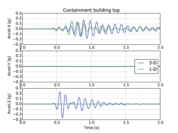
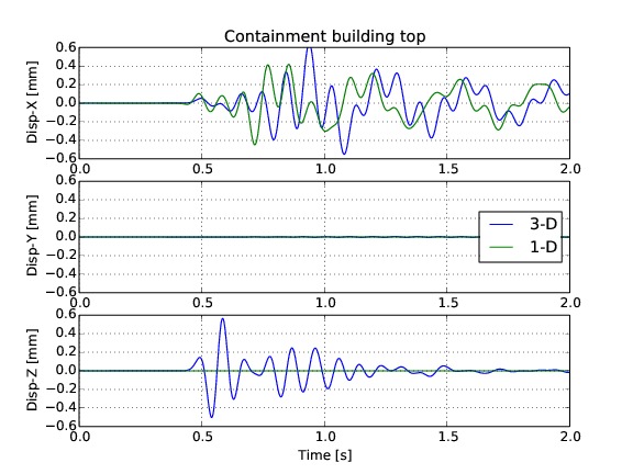
Figures below shows resulting accelerations and displacements at the top of containment building.
On the other hand, Figures below shows resulting accelerations and displacements at top corner of auxiliary building.


Important notes:
- Accelerations and displacements, motions in general, and NPP response, of 6C and 1C cases are quite different. In some cases 1C case gives bigger influences, while in other, 6C case gives bigger influences.
- Differences are particularly obvious in vertical direction, which are much bigger in 6C case.
- Some accelerations of 6C case are larger that those of a 1C case. On the other hand, some displacements of 1C case are larger than those of a 6C case. This just happens to be the case for given source motions, a Ricker wavelet, for given geologic layering and for a given wave speed, and wave length/frequency. There might, will be cases, for different combinations of model parameters, where 1C motions model will produce larger influences than 6C motions model, however motions will certainly again be quite different. There will also be cases where 6C motions will produce larger influences than 1C motions. These differences will have to be analyzed on a case by case basis.
In conclusion, response of an NPP will be VERY DIFFERENT when realistic 6C motions are used, as opposed to a case when 1C, simplified motions are used.
All presented examples and results were developed using Real-ESSI Simulator .
For more information, please contact Boris Jeremić